Week 4: Electronics Production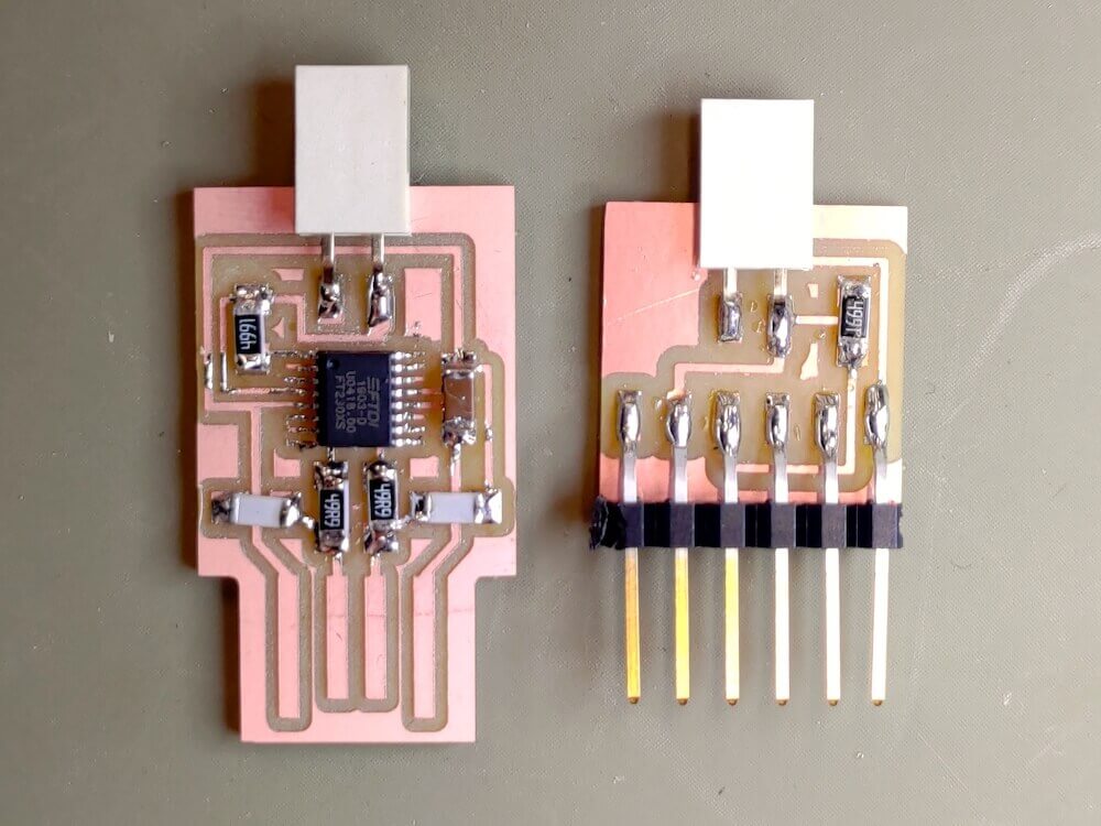
#mods #PCB Milling #SMD Soldering
Assignments: (Group) 1. Characterise the design rules for your PCB production process: document feeds, speeds, plunge rate, depth of cut (traces and outline) and tooling. (Individual) 2. Document your work. 3. Make an in-circuit programmer by milling and stuffing the PCB, test it, then optionally try other PCB fabrication process.
Published on: Feb 19, 2020Last updated on: Jan 12, 2021
Individual Assignment: In-circuit Programmer PCB Milling & Stuffing
Materials
| # | Name |
|---|---|
| 1 | 3D Milling Machine: Roland SRM-20 (Manual) |
| 2 | Soldering Iron |
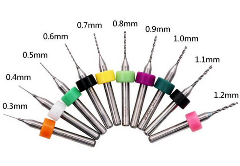
| 3 | 0.3mm, 0.4mm, 0.8mm PCB Milling Bits |
| 4 | Single Sided Copper Clad Laminate |
Setup: Convert PNG Circuit Images to Bit Toolpaths in mods
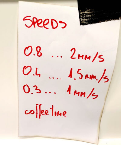
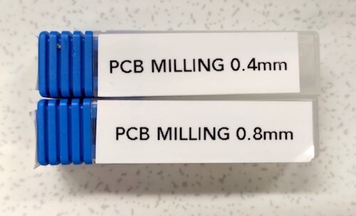
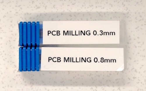
I used hello.serial-UPDI.FT230X and hello.USB-UPDI.FT230X file for my PCB milling fabrication. For milling the traces, we are going to use 0.4mm diameter bit for the former one and 0.3mm for the latter one to remove some of the top copper and then form the final circuit. The bit with 0.8mm diameter is used to cut off the interior (outline) of both boards. Each bit with different diameter has its own suitable cutting speed:
- 0.3mm bit: tiny traces
- 0.4mm bit: normal traces
- 0.8mm bit: interior (outline)
hello.serial-UPDI.FT230X: 0.4mm (traces), 0.8mm (interior)
hello.USB-UPDI.FT230X: 0.3mm (traces), 0.8mm (interior)
mods Toolpath Setting Comparison (SRM-20)
Link to tutorial of MDX-40 milling machine
- origin: (x, y, z) = (0, 0, 0) mm
- home: (x, y, z) = (0, 0, 5) mm
| tool diameter | cut depth | max depth | offset number | speed | file | color |
|---|---|---|---|---|---|---|
| 0.3mm | 0.1mm | 0.1mm | 4 | 1.0mm/s | USB-FT230XS-UPDI.traces.png |
|
| 0.4mm | 0.1mm | 0.1mm | 4 | 1.5mm/s | FTDI-UPDI.traces.png |
|
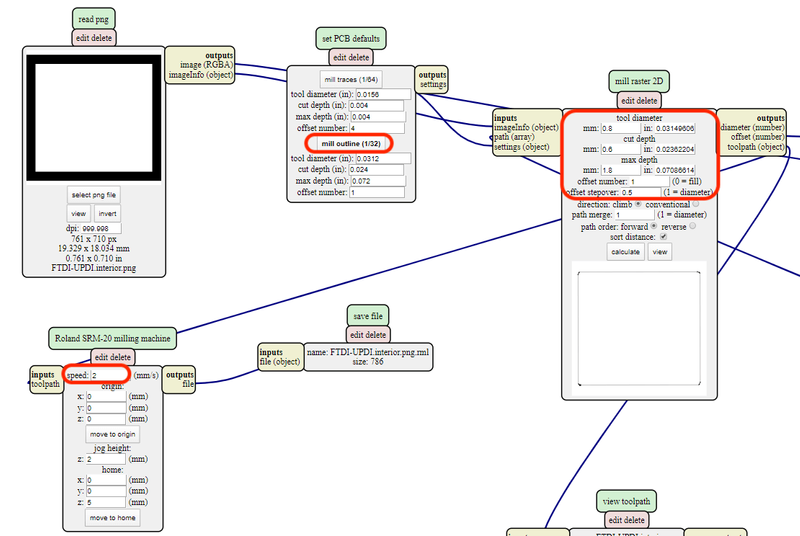
| 0.8mm (Outline) | 0.6mm | 1.8mm | 1 | 2.0mm/s |
|
|
| 0.73mm (Drill) | 0.6mm | 1.8mm | 1 | 2.0mm/s |
|
Generate Trace Toolpath
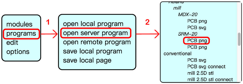
In order to generate the toolpath, I went to the mods website and created the SRM-20 PCB png milling program.
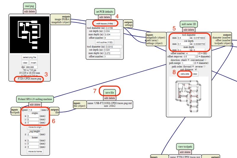
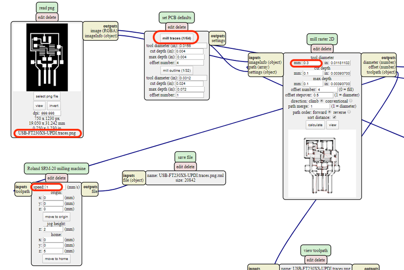
There are total two png files (trace and interior) which form the final circuit. I first uploaded the trace file to mods. Then I did the following steps in order:
- click mill traces (1/64) button
- input parameters in the mill raster 2D module
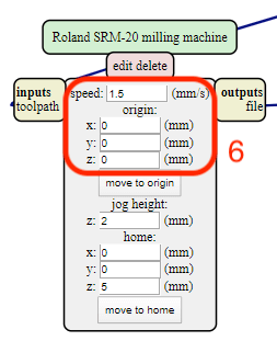
- input the correspondent cutting speed and set the origin to zero
- delete the final WebSocket device module and create a new save file module
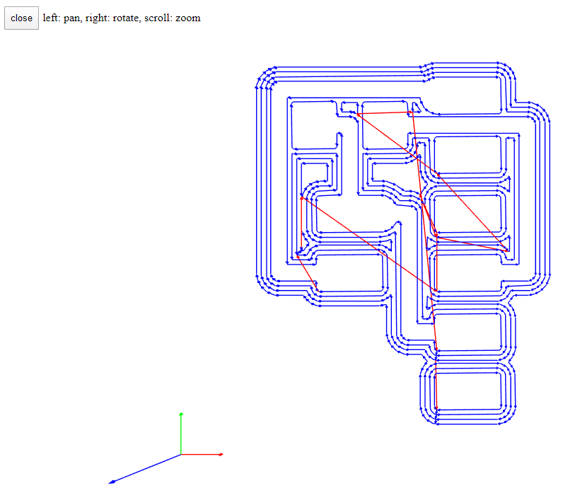
- click the calculate button in the mill raster 2D module
0.4mm Bit Setting (FTDI-UPDI.traces.png)
0.3mm Bit Setting (USB-FT230XS-UPDI.traces.png)
The generated trace toolpath
Generate Interior Toolpath: 0.8mm Bit (USB-FT230XS-UPDI.interior.png, FTDI-UPDI.interior.png)
After generating the trace file, I then uploaded the interior image to mods with the same steps but different parameters to save the outline cutting toolpath file.
Fabrication: SRM-20 Milling Machine
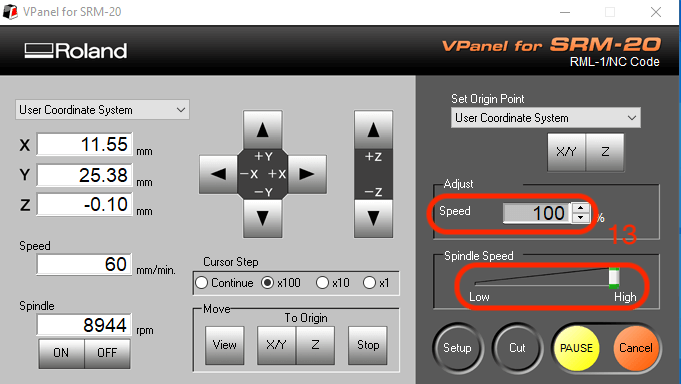
After downloading the rml trace and interior toolpath file, I installed the correspondent bit and turned to the SRM-20 control panel to set up the cutting preference:
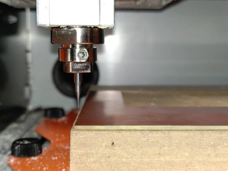
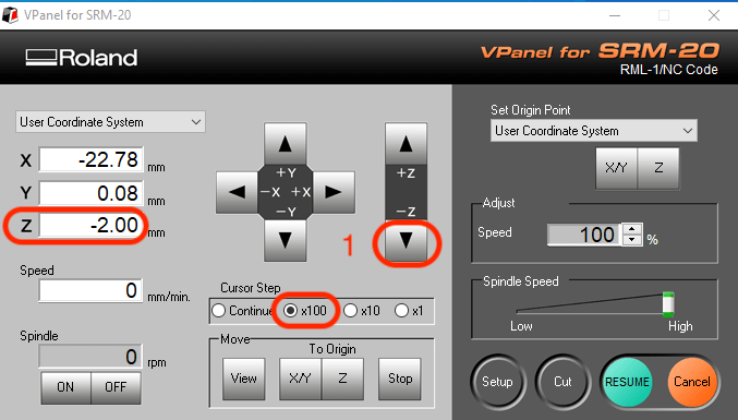
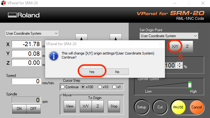
I moved z-axis to reach its lowest point by clicking the downward arrow in first Continue steps then x100 tiny steps. After that, I set the z-axis to zero.
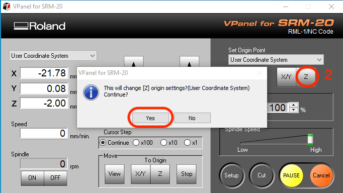
Then I lifted up the z-axis for 2mm and set it to zero again as well as both x-axis and y-axis.
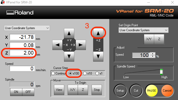
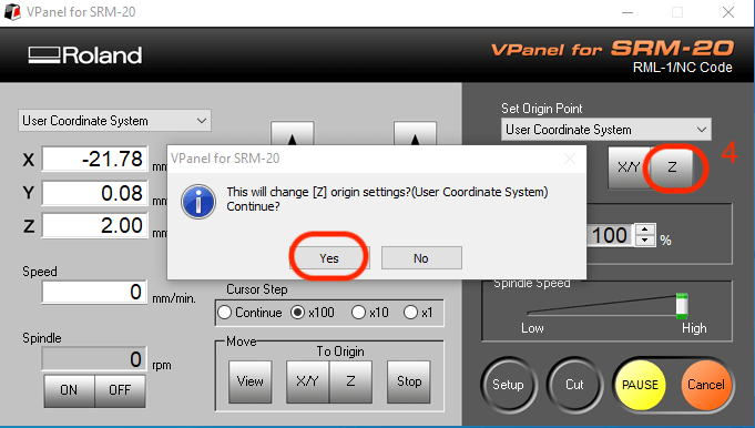
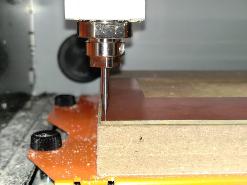
I turned to the milling machince and released the screw to make the bit lower enough to touch the top of the board.

Before starting cutting, I lifted up the z-axis again for 2mm, slowed down the initial cutting and spindle speed and then pressed Cut button. In order to make the job queue clean, I first Delete All jobs and then Add the new one. After that, I clicked Output to cut the traces or the outline.
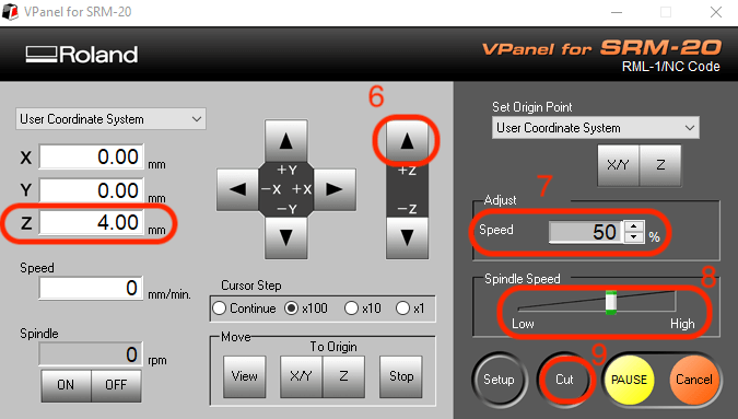
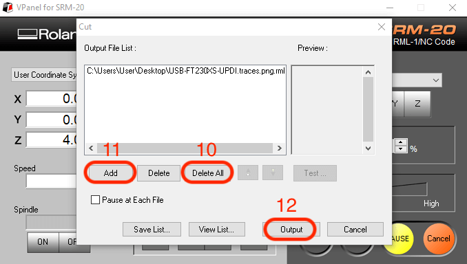
If there is not any problem with the initial cutting, I then adjusted the values of both speeds to normal.
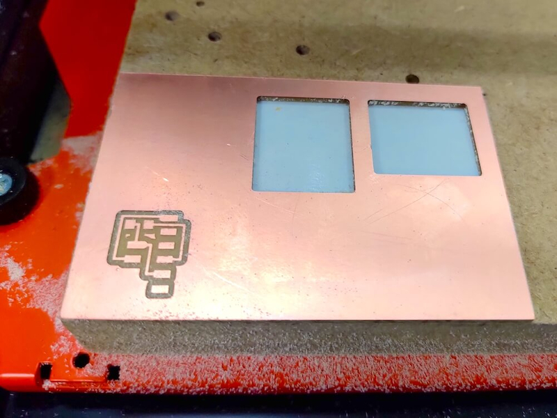
hello.serial-UPDI.FT230X
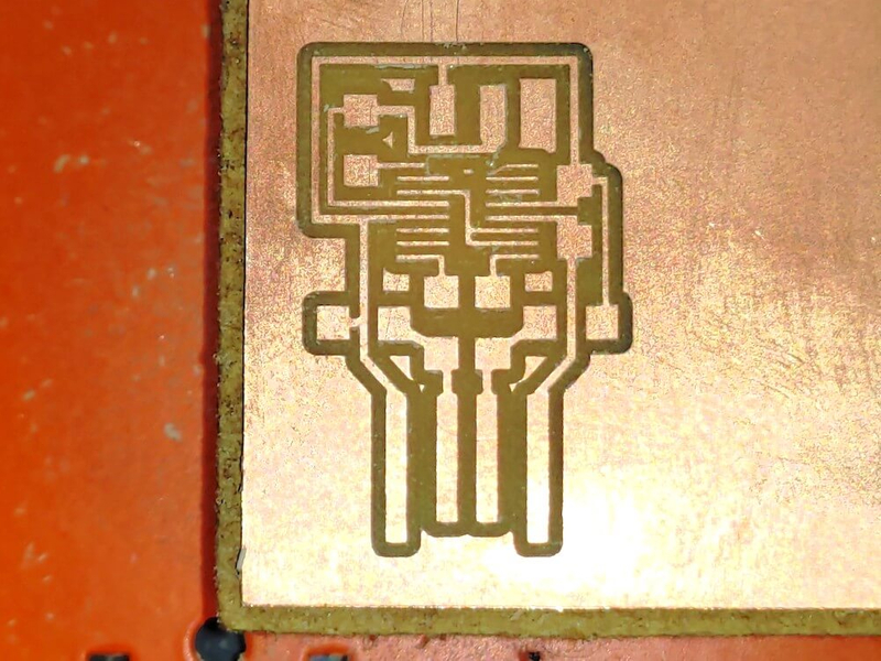
hello.USB-UPDI.FT230X
Assembling & Soldering
Electronic Components
| board | SMD IC | SMD resistor | SMD capacitor | SMD header |
|---|---|---|---|---|
| hello.serial-UPDI.FT230X | - | 4.99k Ω * 1 | - |
|
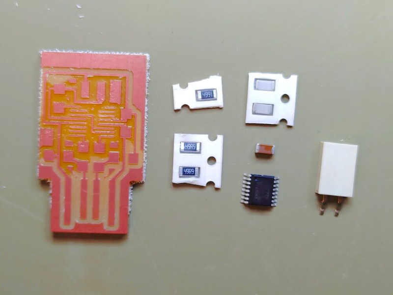
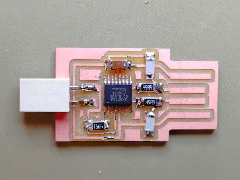
| hello.USB-UPDI.FT230X | FT230XS |
|
|
2W 2.54mm PTH SOCKET SIL SMT * 1 |
It is harder to solder SMD components than the DIP ones. Therefore, I used a magnifier to make sure that I can clearly see each pin of the components while soldering the bords especially the SMD IC.
Hero Shot: hello.serial-UPDI.FT230X
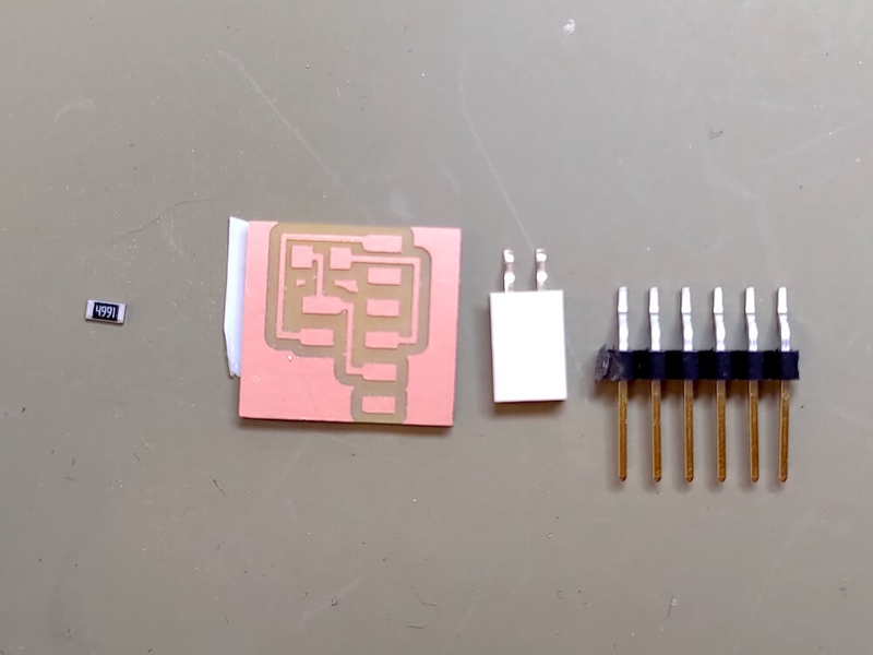
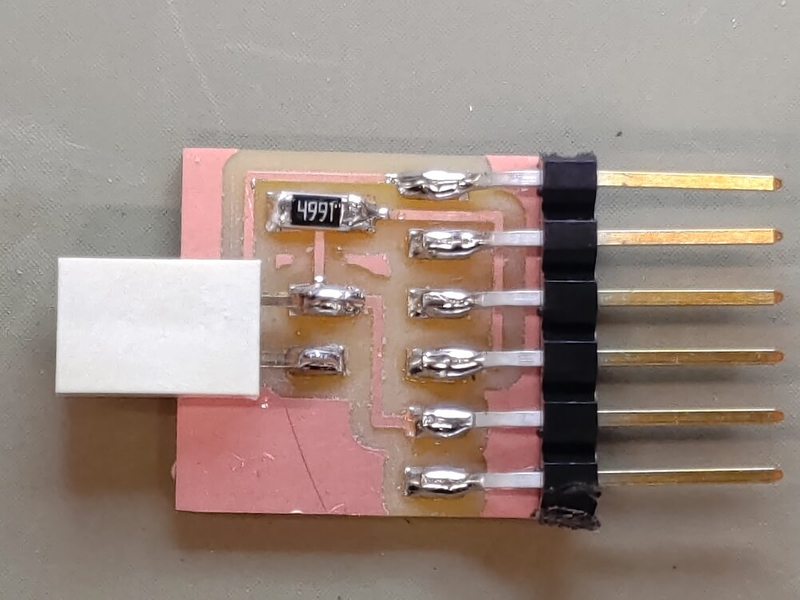
Hero Shot: hello.USB-UPDI.FT230X
Problem & Solution
I spent a lot of time on adjusting the origin of the z-axis of the SRM-20 milling machine since it didn't actually cut through the copper layer but lifted up after pessing the Output button at the beginning. Then I found out that the problem is that the origin value of the Roland SRM-20 milling machine module which I didn't change but left it as default values (10, 10, 10) on the mods website had made the machine lift up for 10mm during the cutting process.
Program the Board
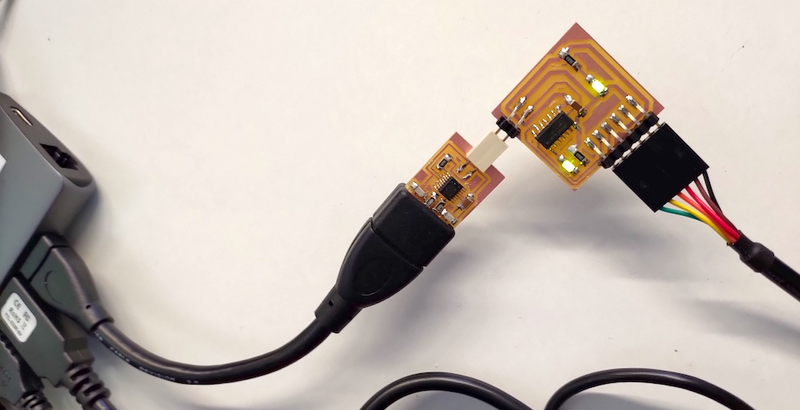
I programmed the Hello ATtiny1614 Blink board with the hello.USB-UPDI.FT230X I made by uploading the Arduino script through the command lines in the terminal. Finally, my board works!

