Week 13: Networking and Communications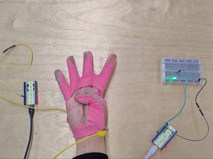
#ESP32 #Conductive Fabrics
Assignments: (Group) 1. Send a message between two projects. (Individual) 2. Design, build, and connect wired or wireless node(s) with network or bus addresses.
Published on: Nov 12, 2020Last updated on: Jan 12, 2021
Individual Assignment: ESP32 Wireless One-Way Communication Project - Button + LED
For the wireless communication, I adapted ESP32 microcontoller which is a series of low-cost, low-power system on a chip microcontrollers with integrated Wi-Fi and dual-mode Bluetooth. By following the steps found in Random Nerd Tutorials website, I aqccuires ESP-NOW techniques for building one-way or two-way communication without connecting to any Wi-Fi.

Materials
| # | Name | Source | Description |
|---|---|---|---|
| 1 | NodeMCU-32S ESP32 * 2 | DigiKey | Main microcontrollers for wirelss communication. |
| 2 | Button | - | Used for input trigger. |
| 3 | LED | - | Used for output feedback. |
| 4 | Micro USB * 2 | - | Connected to microcontrollers for programming or powering purpose. |
| 5 | Power Bank | - | Used for portable purpose. |
| 6 | Breadboards * 2 | - | Used for prototyping. |
| 7 | 10kΩ, 220Ω Resistor * 1 | - | Connected to a button and a LED respectively. |
| 8 | Conductive Fabrics | - | Connected to built-in touch sensors to form touch buttons. |
| 9 | Jumper Wires, Alligator Clips | - | - |
Build
Pin Functions
Since ESP32 has around 40 GPIOs, I made a table for understanding the function of each pin easily.


Pin Connection
I started with building the simplest one-way wireless communication by connecting one button to one of the ESP32 mircocontrollers and one LED to the other one.
ESP32 Button Sender
The ESP32 with a button connected to pin 15 works as a signal sender which will remotely trigger the other microcontroller to light up the LED.


ESP32 LED Receiver
For easy observation, I connected a LED to the ESP32 receiver for tracing the signal sent from the input button connected to the ESP32 sender. Since there is a built-in LED on pin 2, we can also just use it as the output without connecting any other LED to the receiver.


Programming
I followed the steps from the Installing the ESP32 Board in Arduino IDE (Mac OS X and Linux instructions) tutorial to set up my ESP32 programming environment properly.
Set Up Programming Environment (Arduino IDE)
Step 1. Add Board Data Path to the Arduino IDE Preferences
Type https://dl.espressif.com/dl/package_esp32_index.json into the Additional Board Manager URLs field in the Preferences window (Arduino → Preferences) and then click the OK.

Step 2. Install the ESP32 board to the Arduino IDE
Type esp32 text in Board Manager (Tools → Board → Board Manager) and install it.

Step 3. Select corresponding ESP32 type and start programming

Step 4. Press the IO0 button on ESP32 while uploading the code

Code
In order to make the wireless communication stable between two ESP32 microcontrollers during the interaction, I applied ESP-NOW to the code instead of Wi-Fi protocol. With ESP-NOW, the boards can automatically pair each other and remain persistent if suddenly one of the boards loses power or resets without manually reconfiguring the floating Wi-Fi IP.
In simple words, ESP-NOW is a fast communication protocol that can be used to exchange small messages (up to 250 bytes) between ESP32 boards.

Get ESP32 Board MAC Address
Before starting to make the one-way communication between two boards with ESP-NOW, I first needed to find out the MAC address of the receiver board. A media access control address (MAC address) is a unique identifier assigned to a network interface controller (NIC) for use as a network address in communications within a network segment.
Each ESP32 has a unique MAC Address and that is how we identify each board to send data to it using ESP-NOW. With the following code, I can get the MAC address of the ESP32 board connected to my computer from the Serial Monitor window.
#include "WiFi.h"

void setup(){
  Serial.begin(115200);
  WiFi.mode(WIFI_MODE_STA);
  Serial.println(WiFi.macAddress());
}

void loop(){

}
ESP32 Button Sender
After getting the MAC address of the ESP32 receiver board, I started to program the code for ESP32 sender and replaced the original MAC address with the corresponding one.
Function Name and Description
esp_now_init()Initializes ESP-NOW. You must initialize Wi-Fi before initializing ESP-NOW.esp_now_add_peer()Call this function to pair a device and pass as argument the peer MAC address.esp_now_send()Send data with ESP-NOW.esp_now_register_send_cb()Register a callback function that is triggered upon sending data. When a message is sent, a function is called – this function returns whether the delivery was successful or not.esp_now_register_rcv_cb()Register a callback function that is triggered upon receiving data. When data is received via ESP-NOW, a function is called.
#include <esp_now.h>
#include <WiFi.h>

// REPLACE WITH YOUR RECEIVER MAC Address
uint8_t broadcastAddress[] = {0x24, 0x6F, 0x28, 0x7A, 0xA0, 0xF4};

#define BUTTON 15 // digital pin

int myData; //buttonState

// callback when data is sent
void OnDataSent(const uint8_t *mac_addr, esp_now_send_status_t status) {
  Serial.print("\r\nLast Packet Send Status:\t");
  Serial.println(status == ESP_NOW_SEND_SUCCESS ? "Delivery Success" : "Delivery Fail");
}

void setup() {
  pinMode(BUTTON, INPUT);

  // Init Serial Monitor
  Serial.begin(115200);

  // Set device as a Wi-Fi Station
  WiFi.mode(WIFI_STA);

  // Init ESP-NOW
  if (esp_now_init() != ESP_OK) {
    Serial.println("Error initializing ESP-NOW");
    return;
  }

  // Once ESPNow is successfully Init, we will register for Send CB to
  // get the status of Trasnmitted packet
  esp_now_register_send_cb(OnDataSent);

  // Register peer
  esp_now_peer_info_t peerInfo;
  memcpy(peerInfo.peer_addr, broadcastAddress, 6);
  peerInfo.channel = 0;
  peerInfo.encrypt = false;

  // Add peer
  if (esp_now_add_peer(&peerInfo) != ESP_OK){
    Serial.println("Failed to add peer");
    return;
  }
}

void loop() {
  // Send message via ESP-NOW
  esp_err_t result = esp_now_send(broadcastAddress, (uint8_t *) &myData, sizeof(myData));

  if (result == ESP_OK) {
    Serial.print("Sent with success, Button State: ");
  }
  else {
    Serial.println("Error sending the data");
  }

  Serial.println(myData);
  delay(200);
}
How the code works
First, I included the esp_now.h and WiFi.h libraries and then inserted the MAC address of my ESP32 receiver.
#include <esp_now.h>
#include <WiFi.h>

uint8_t broadcastAddress[] = {0x24, 0x6F, 0x28, 0x7A, 0xA0, 0xF4};
After that, I defined which pin is connected to the button and created a variable called myData to hold the button HIGH/LOW state.
#define BUTTON 15 // digital pin
int myData; //buttonState
Following, I defined the OnDataSent() function which is a callback function that will be executed when a message is sent. The Serial Monitor here will print Delivery Success if the message is successfully delivered, otherwise it will print Delivery Fail.
// callback when data is sent
void OnDataSent(const uint8_t *mac_addr, esp_now_send_status_t status) {
  Serial.print("\r\nLast Packet Send Status:\t");
  Serial.println(status == ESP_NOW_SEND_SUCCESS ? "Delivery Success" : "Delivery Fail");
}
Next, in the setup() function, I first set the button pin to INPUT, initialized the serial monitor for debugging, set the device as a Wi-Fi station and initialized ESP-NOW.
pinMode(BUTTON, INPUT);

// Init Serial Monitor
Serial.begin(115200);

// Set device as a Wi-Fi Station
WiFi.mode(WIFI_STA);

// Init ESP-NOW
if (esp_now_init() != ESP_OK) {
    Serial.println("Error initializing ESP-NOW");
    return;
}
After that, I registered for the OnDataSent() callback function created previously to print the message of delivery and paired with another ESP-NOW device to send data.
// Once ESPNow is successfully Init, we will register for Send CB to
// get the status of Trasnmitted packet
esp_now_register_send_cb(OnDataSent);

// Register peer
esp_now_peer_info_t peerInfo;
memcpy(peerInfo.peer_addr, broadcastAddress, 6);
peerInfo.channel = 0;
peerInfo.encrypt = false;

// Add peer
if (esp_now_add_peer(&peerInfo) != ESP_OK){
    Serial.println("Failed to add peer");
    return;
}
In the loop(), I will send a message (button state) via ESP-NOW every 0.2 second.
esp_err_t result = esp_now_send(broadcastAddress, (uint8_t *) &myData, sizeof(myData));And then I checked if the message was successfully sent or not.
if (result == ESP_OK) {
    Serial.print("Sent with success, Button State: ");
}
else {
    Serial.println("Error sending the data");
}
The loop() is executed every 200 milliseconds (0.2 second).
delay(200);ESP32 LED Receiver
For the ESP32 receiver, I connected a LED to pin 2 for easily observing the remote button state.
#include <esp_now.h>
#include <WiFi.h>

#define LED 2
int myData = 0;

// callback function that will be executed when data is received
void OnDataRecv(const uint8_t * mac, const uint8_t *incomingData, int len) {
  memcpy(&myData, incomingData, sizeof(myData));
  Serial.println(myData);

  // change the analog out value:
  digitalWrite(LED, myData);
}

void setup() {
  pinMode(LED, OUTPUT);

  // Initialize Serial Monitor
  Serial.begin(115200);

  // Set device as a Wi-Fi Station
  WiFi.mode(WIFI_STA);

  // Init ESP-NOW
  if (esp_now_init() != ESP_OK) {
    Serial.println("Error initializing ESP-NOW");
    return;
  }

  // Once ESPNow is successfully Init, we will register for recv CB to
  // get recv packer info
  esp_now_register_recv_cb(OnDataRecv);
}

void loop() {

}
How the code works
Similarly to the sender, I started by including the libraries, defined the LED pin and created a variable called myData to get the remote button state.
#include <esp_now.h>
#include <WiFi.h>

#define LED 2
int myData = 0;
Next, I created a callback function onDataRecv() that will be called when the ESP32 receives the data via ESP-NOW, accept the button state in the specific data type and light up the LED according to the received button state (myData).
// callback function that will be executed when data is received
void OnDataRecv(const uint8_t * mac, const uint8_t *incomingData, int len) {
  memcpy(&myData, incomingData, sizeof(myData));
  Serial.println(myData);

  // change the analog out value:
  digitalWrite(LED, myData);
}
In the setup(), I intialized the Serial Monitor, set the device as a Wi-Fi Station, initialized ESP-NOW and then registered for a previously created callback function OnDataRecv() that will be called when data is received.
void setup() {
  pinMode(LED, OUTPUT);

  // Initialize Serial Monitor
  Serial.begin(115200);

  // Set device as a Wi-Fi Station
  WiFi.mode(WIFI_STA);

  // Init ESP-NOW
  if (esp_now_init() != ESP_OK) {
    Serial.println("Error initializing ESP-NOW");
    return;
  }

  // Once ESPNow is successfully Init, we will register for recv CB to
  // get recv packer info
  esp_now_register_recv_cb(OnDataRecv);
}
End Result
Problem & Solution
Sometimes the timing of pressing the IO0 button shown above on the ESP32 is a little bit tricky to predict and thus it throws out an error while uploading the code to the microcontroller through Arduino IDE . The solutions I found include:
- First press the EN/Reset button then press the IO0 button while uploading the code to ESP32.
- Unplug and plug again the micro USB connected to the ESP32 microcontroller and then start uploading the code.
Group Assignment: Send a message between two projects
Link to Documentation Page

Build: ESP32 Wireless Two-Way Communication Project - Built-in Touch Sensors + Conductive Fabrics + LED
Pin Connection
Since both ESP32 act as a sender and a receiver at the same time, I connected a LED and one piece of conductice fabrics to the same pins of each ESP32 for easily programming. (Note. Make sure to connect the conductive fabric to Touch Sensor Pins introduced above.)

Interaction
The green LED was lighted up while I touched the conductive fabric connected to the opposite ESP32.

While I pressed the conductive fabric connected to the other ESP32, it lighted up the yellow LED connected to the previous one.

Programming
How to set up the programming environment for ESP32 can be found from the above section of Week 13: Networking and Communications.
For two-way communication, both ESP32 boards use the same code but different MAC addresses to work as a sender and a receiver simultaneously. I followed the ESP-NOW Two-Way Communication Between ESP32 Boards tutorial and adjusted the code the form the following interaction.

#include <esp_now.h>
#include <WiFi.h>
#include <analogWrite.h>

// REPLACE WITH the MAC Address of THE OPPOSITE BOARDuint8_t broadcastAddress[] = {0x24, 0x6F, 0x28, 0x7A, 0xA0, 0xF4};  // ESP32 #1//uint8_t broadcastAddress[] = {0x24, 0x6F, 0x28, 0x7A, 0xB1, 0x78}; // ESP32 #2

#define PIEZO 4 // Touch Sensor pin: analog (0-4095)
#define LED 16 // PWM pin

const int rangeMax = 35;
const int rangeMin = 6;
int sensorValue = 0;        // value read from the touch sensor connected to conductive fabric
int outputValue = 0;        // value output to the PWM (analog out)

int myData; // Sensor State

// callback when data is sent
void OnDataSent(const uint8_t *mac_addr, esp_now_send_status_t status) {
  Serial.print("\r\nLast Packet Send Status:\t");
  Serial.println(status == ESP_NOW_SEND_SUCCESS ? "Delivery Success" : "Delivery Fail");
}

// callback function that will be executed when data is received
void OnDataRecv(const uint8_t * mac, const uint8_t *incomingData, int len) {
  memcpy(&myData, incomingData, sizeof(myData));
  Serial.print("LED Value: ");
  Serial.println(myData);

  // change the analog out value:
  analogWrite(LED, myData);
}


void setup() {
  // Init Serial Monitor
  Serial.begin(115200);

  // Set device as a Wi-Fi Station
  WiFi.mode(WIFI_STA);

  // Init ESP-NOW
  if (esp_now_init() != ESP_OK) {
    Serial.println("Error initializing ESP-NOW");
    return;
  }

  // Once ESPNow is successfully Init, we will register for Send CB to
  // get the status of Trasnmitted packet
  esp_now_register_send_cb(OnDataSent);

  // Register peer
  esp_now_peer_info_t peerInfo;
  memcpy(peerInfo.peer_addr, broadcastAddress, 6);
  peerInfo.channel = 0;
  peerInfo.encrypt = false;

  // Add peer
  if (esp_now_add_peer(&peerInfo) != ESP_OK){
    Serial.println("Failed to add peer");
    return;
  }

  // Register for a callback function that will be called when data is received
  esp_now_register_recv_cb(OnDataRecv);
}

void loop() {
  getSensorValue();

  // Send message via ESP-NOW
  esp_err_t result = esp_now_send(broadcastAddress, (uint8_t *) &outputValue, sizeof(outputValue));

  if (result == ESP_OK) {
    Serial.print("Sent with success, Sensor Value: ");
  }
  else {
    Serial.println("Error sending the data");
  }

  Serial.print(sensorValue);
  delay(200);
}

void getSensorValue() {
  sensorValue = touchRead(PIEZO);
  sensorValue = (sensorValue > rangeMax) ? rangeMax : sensorValue;
  // map it to the range of the analog out:
  outputValue = map(sensorValue, rangeMax, rangeMin, 0, 255);
}
How the code works
The code combines the functions from both sender and receiver introduced above. Except these, I replaced the button whose state can be read with digitalRead function with conductive fabrics connected to Touch Sensors whose analog state can only be read with touchRead() function with the value ranging from 0-4095.
According to this, I first defined which Touch Sensor is connected to conductive fabric and called it PIEZO pin and then connected the LED to a PWM pin which can analogWrite() the value ranging from 0-255 instead of 0 or 1 (HIGH or LOW).
#define PIEZO 4 // Touch Sensor pin: analog (0-4095)
#define LED 16 // PWM pin

const int rangeMax = 35;
const int rangeMin = 6;
int sensorValue = 0;        // value read from the touch sensor connected to conductive fabric
int outputValue = 0;        // value output to the PWM (analog out)

int myData; // Sensor State
Next, I created a function called getSensorValue() put in the loop() to first touchRead() the value from the Touch Sensor, mapped the value from 0-4095 to 0-255 and then analogWrite() to the LED. Sometimes it is better to narrow down the range of Touch Sensor by defining a threshold to fillter out the changing scope.
void getSensorValue() {
  sensorValue = touchRead(PIEZO);
  sensorValue = (sensorValue > rangeMax) ? rangeMax : sensorValue;
  // map it to the range of the analog out:
  outputValue = map(sensorValue, rangeMax, rangeMin, 0, 255);
}
End Result
