Week 5: 3D Scanning and Printing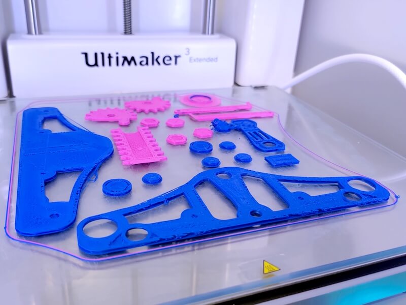
#Fusion360 #Cura #Ultimaker 2+ Extended
Assignments: (Group) 1. Test the design rules for your 3D printer(s). 2. Document your work and explain what are the limits of your printer(s). (Individual) 3. Design and 3D print an object (small, few cm3, limited by printer time) that could not be made subtractively. 4. 3D scan an object (and optionally print it).
Published on: Feb 26, 2020Last updated on: Jan 12, 2021
Group Assignment: Test the design rules for your 3D printer(s)
Link to Documentation Page
Individual Assignment: 3D Printing
Materials
| # | Name |
|---|---|
| 1 | 3D Printer: Ultimaker 2+ Extended (Manual) |
| 2 | 1.75mm PLA Filament |
CURA Software Setup
I downloaded an open-source STL model from Thingiverse for testing the limitation of our printer.

After importing the model to CURA, I did some correspondent settings within the software before converting the STL file to gcode file for printing:
- Set the Layer Height to 0.2mm. (ps. The printing time is longer with smaller layer height/resolution.)

- Set the Wall Thickness to 1mm. (ps. The printing time is longer with thicker walls.)

- Set the Infill Density to 15%. (ps. The printing time is longer with more infill desity.)

- Set the Build Plate Adhesion Type to Skirt or Brim. (ps. The printing time is longer with Raft.)

- Set the Print Speed to 150mm/s which is within the range indicated in the datasheet. After every setting is done, click Preview to double check to nozzle movement with simulation.


- Click Save to Removable Device to export the gcode file to a USB flash drive for standalone printing.


Printing Steps

Here are the steps about how to use Ultimaker 2+ Extended to print models with single color after exporting the gcode file:
- Power on the printer.

- Select Material in the menu to change the filament.

- Click Change.

- Wait for the printer to heat up its nozzle.

- Choose which filament to use for printing.

- Click Ready to let the printer extract the original filament.

- Pull out the filament.

- Use the tool to cut the head of the filament to flat.


- Insert the filament in to the hole manually.

- Select the type of the filament (Here: PLA).

- Click Ready to let the printer suck the filament.


- Click Ready after the printer extrudes the filament from its nozzle.

- Back to the home menu and click Print.

- Select a gcode file for printing.

- Wait for the printer to heat up.

- The printer is printing the first layer. The filament I inserted is white whereas the leftover of the previous filament is blue.


- Remove the model with a blunt knife.


Single-Color Model (Ultimaker 2+ Extended)


Since the white model was too bright to see the printing details, I re-printed the same model with orange filament.

We can see from the diagrams that the filament starts to fall when the printing angle is greater than 70 degrees.


Dual-Color Model (Ultimaker 3 Extended)
I also tried to print a set of models in dual colors at once with Ultimaker 3 Extended.

Individual Assignment: 3D Scanning
Materials
| # | Name |
|---|---|
| 1 | Artect 3D Scanner |
| 2 | A 3D object for scanning |
Artect Studio Software Setup (Manual) & Scanning Steps
- Open the application.

- Click the Scan button on the sidebar.

- Connect the 3D scanner to a computer.

- After detecting the 3D scanner, check the Real-time fusion and click Preview.

- Hold the scanner and palce the model on a spinning table.

- Click Record to start scanning.


- Click Stop to end scanning and start to visualize the model in the application.


- The model with multiple layers.

- Only activate the Fusion layer.


- Remove unwanted area.
a. Method 1: Click Editor on the sidebar to erase nosies manually.

b. Method 2: Click Small-object filter within the Tools sub-menu to automatically remove nosies.

- Click Hole filling to complete the model.

- Export the scanning model as a STL file for 3D printing.

- Check the STL file in a 3D viewer.


