Week 8: Embedded Programming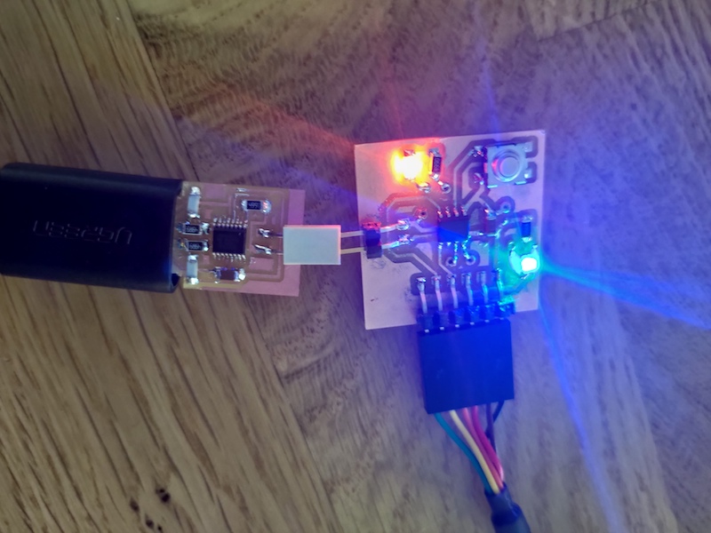
#Python #Arduino IDE #pyUPDI #megaTinyCore
Assignments: (Group) 1. Compare the performance and development workflows for different microcontroller families. (Individual) 2. Read the datasheet for the microcontroller you are programming. 3. Program the board you have made to do something, with as many different programming languages and programming environments as possible.
Published on: Mar 18, 2020Last updated on: Jan 12, 2021
-
Individual Assignment: ATtiny 412 Double-Sided Board Programming
- Materials
- Port Manipulation Comparison (megaTinyCore)
-
Set up Programming Environment (megaTinyCore + pyUPDI + Arduino IDE)
- Step 1. Connect both boards to a USB hub and install both VCP and D2XX drivers for a computer to detect FTDI devices (p.s. Wacom drivers might affect the FTDI detection.)
- Step 2. Type
ls /dev/tty.*command in the terminal to find out both FTDI and UPDI ports - Step 4. Add the build path to the Arduino preference.txt for saving the compiled hex file
- Step 5. Restart Arduino IDE and choose which type of the ATtiny boards you want to program in the tool menu and its settings to start programming
- Step 6. Start programming the code in Arudino IDE and compile it to generate a hex file in the build subfolder
- Step 7. Install Python3 with pyenv
- Step 8. Install pyserial and pyupdi packages via pip command
- Step 9. Upload the compiled hex file to the ATtiny 412 board via pyupdi
-
Group Assignment: Compare the performance and development workflows between different AVR boards
Individual Assignment: ATtiny 412 Double-Sided Board Programming

Materials
| # | Name | Source | Description |
|---|---|---|---|
| 1 | ATtiny 412 Double-Sided Board | Week 6: Electronics Design | The main board for programming. |
| 2 | USB FTDI FT230XS Host Board | Aalto Fablab | Used for replacing a FTDI cable . |
| 3 | USB UPDI FT230XS Programmer | Aalto Fablab | Used as a 2-pin programmer board for uploading the code to the main ATtiny 412 board through it. |
| 4 | USB Extension Cable | Amazon | Used for connecting to the USB UPDI FT230XS Programmer. |
| 5 | USB Hub | Amazon | - |
Read a Microcontroller Datasheet
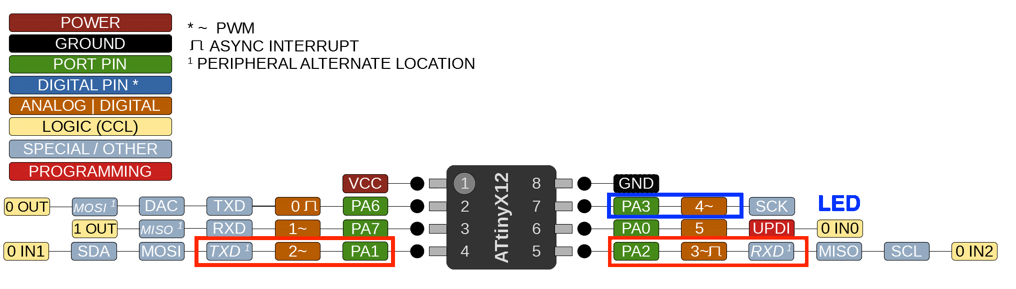
From the ATtiny 412 datasheet, I learnt that each pin has different functions (e.g., in addtion to normal I/O, PA1 and PA2 can also be used as TX and RX for serial communication with a computer. PA0 can be connected to a UPDI programmer for uploading a hex file.) With the code below, the ATtiny 412 board can read the input text from Arduino Serial Monior through a FTDI cable or host board withouting connecting any other I/O devices.


ATtiny412_echo.ino
#define max_buffer 25

static int index = 0;
static char chr;
static char buffer[max_buffer] = {0};

void setup() {
   Serial.begin(115200);
}

void loop() {
   if (Serial.available() > 0) {
      chr = Serial.read();
      Serial.print("hello.t412.echo: you typed \"");
      buffer[index++] = chr;
      if (index == (max_buffer-1))
         index = 0;
      Serial.print(buffer);
      Serial.println("\"");
      }
}
The datasheet also shows how to control the pins in a faster way by setting certain port registers to 0 (Low) or 1 (High).
Port Manipulation Comparison (megaTinyCore)
Here I use PA3 for example:
| Function | Register | Arduino |
|---|---|---|
| Output |
PORTA.DIRSET = PIN3_bm; PORTA.OUTSET = PIN3_bm; |
pinMode(4, OUTPUT); |
| Input | PORTA.DIRCLR = PIN3_bm; | pinMode(4, INPUT); |
| High | PORTA.OUT |= PIN3_bm; | digitalWrite(4, HIGH); |
| Low | PORTA.OUT &= ~PIN3_bm; | digitalWrite(4, LOW); |
There are two ways to specify the ATtiny 412 pins in Arduino IDE. One is to use their original names shown below:
ATtiny 412 Pins


ATtiny412_blink.ino
#include <avr/io.h>

#define LED_AVR PIN3_bm //PA3: LED pin

void setup() {
   PORTA.DIRSET = LED_AVR;
}

void loop() {
  PORTA.OUT |= LED_AVR;
  delay(100);
  PORTA.OUT &= ~LED_AVR;
  delay(100);
 }
The other is to map the ATtiny 412 pins to the Arduino pin numbers with the megaTinyCore library installed so that we can simplify the code shown below:
ATtiny 412 Pins (mapped to Arduino pin numbers)
ATtiny412_blink_simplified.ino
#define LED_AVR 4 //PA3: LED pin

void setup() {
  pinMode(LED_AVR, OUTPUT)
}

void loop() {
  digitalWrite(LED_AVR, HIGH);
  delay(100);
  digitalWrite(LED_AVR, LOW);
  delay(100);
}
Set up Programming Environment (megaTinyCore + pyUPDI + Arduino IDE)
Step 1. Connect both boards to a USB hub and install both VCP and D2XX drivers for a computer to detect FTDI devices (p.s. Wacom drivers might affect the FTDI detection.)
Step 2. Type ls /dev/tty.* command in the terminal to find out both FTDI and UPDI ports
Here:
- FTDI Host Board:
/dev/tty.usbserial-D3072T22 - UPDI Programmer Board:
/dev/tty.usbserial-D3072T1T

Step 3. Install megaTinyCore Arduino library
Option 1.
Copy and paste this URL http://drazzy.com/package_drazzy.com_index.json from Boards Manager Installation section of the megaTinyCore library to the Arduino preference.

After that, type the megaTinyCore keyword in the Tools -> Board -> Board Manager and install it.

Option 2.
Download megaTinyCore library and unzip it to (MAC) /Users/USER_NAME/Documents/Arduino/hardware (create one if there is no hardware folder).

Step 4. Add the build path to the Arduino preference.txt for saving the compiled hex file
Click the link shown in the Arduino preference to enter the preference.txt and add the following new line.

Step 5. Restart Arduino IDE and choose which type of the ATtiny boards you want to program in the tool menu and its settings to start programming


Step 6. Start programming the code in Arudino IDE and compile it to generate a hex file in the build subfolder
After finishing coding, click the verify button to comile the hex file which will be uploaded via pyupdi libray in the terminal.

Step 7. Install Python3 with pyenv
pyenv is a wonderful tool for managing multiple Python versions. Even if you already have Python installed on your system, it is worth having pyenv installed so that you can easily try out new language features or help contribute to a project that is on a different version of Python.
Follow the order below to install python properly:
git clone https://github.com/pyenv/pyenv.git ~/.pyenvdownload pyenv from GitHubecho 'export PYENV_ROOT="$HOME/.pyenv"' >> ~/.zshrcassign its envrionment paths in the .zshrc (or .bashrc) profileecho 'export PATH="$PYENV_ROOT/bin:$PATH"' >> ~/.zshrcecho -e 'if command -v pyenv 1>/dev/null 2>&1; then\n eval "$(pyenv init -)"\nfi ' >> ~/.zshrcexec "$SHELL"pyenv install 3.7.7install the specific python version you prefer (Here: 3.7.7)pyenv global 3.7.7switch to the installed version (Here: 3.7.7)
Other useful pyenv commands:
pyenv versionslist all the installed versionspyenv versionlist the version in usepyenv uninstall 3.7.7uninstall certain version (Here: 3.7.7)

Step 8. Install pyserial and pyupdi packages via pip command
pip install pyserialinstall the pyserial packagepip install https://github.com/mraardvark/pyupdi/archive/master.zipinstall the pyupdi packagepyupdicheck pyupdi usage
Other commands for checking installed python packages/modules:
pip freezelist all the installed packagespip freeze | grep pyseriallist the certain installed package (Here: pyserial)

Step 9. Upload the compiled hex file to the ATtiny 412 board via pyupdi
ls /dev/tty.*find out which port is the UPDI programmer board (Here: /dev/tty.usbserial-D3072T1T)pyupdi -d tiny412 -b 115200 -c /dev/tty.usbserial-D3072T1T -f /Users/USER_NAME/Documents/Arduino/build/ATtiny412_blink.ino.hex -vupload the compiled code to the ATtiny 412 board with 115200 baud rate
End Result
The board I redrew finally works after I programmed it.
ATtiny412_blink.ino: blink the LED
ATtiny412_blink_button.ino: blink the LED if the button is pressed
#include <avr/io.h>

#define LED_AVR PIN3_bm //PA3: LED pin
#define BUTTON_AVR PIN6_bm //PA6: Button pin

void setup() {
   PORTA.DIRSET = LED_AVR;
   PORTA.DIRCLR = BUTTON_AVR;
}

void loop() {
  bool state = PORTA.IN & BUTTON_AVR; // read the state of a pin
  switch(state) {
    case 0:
    PORTA.OUT &= ~LED_AVR;
    break;
    case 1:
    PORTA.OUT |= LED_AVR;
    break;
    default:
    PORTA.OUT &= ~LED_AVR;
    break;
  }
 }
Group Assignment: Compare the performance and development workflows between different AVR boards
Link to Documentation Page
AVR Programming: ATtiny 412 + avr-gcc + pyupdi + Terminal
Step 1. Set up Programming Environment
I followed this avr-gcc & avrdude makefile tutorial | Compile C & upload to AVR board (mac) and adjusted some parameters to generate hex code from a elf file (which is generated from a c file) via avr-gcc and then upload the hex file to the ATtiny 412 board via pyupdi.
Follow the order below to install avr-gcc properly:
/bin/bash -c "$(curl -fsSL https://raw.githubusercontent.com/Homebrew/install/master/install.sh)"install Homebrewxcode-select --installinstall Xcodebrew tap osx-cross/avrbrew install avr-gccinstall avr-gcc & install AVR Libcbrew install avrdudeinstall AVR Downloader/Uploader
Step 2. Start Programming C File
hello.412.blink.c
#include <avr/io.h>
#include <util/delay.h>

int main(void) {
    PORTA.DIRSET = PIN3_bm;// or PORTA.DIR = 0b01000000; // Use LED: PA3 as Output
    PORTA.DIRCLR = PIN6_bm;// Use Button: PA6 as Input

    while (1) {
        PORTA.OUT |= LED_AVR;
        _delay_ms(500);
        PORTA.OUT &= ~LED_AVR;
        _delay_ms(500);
    }
}
Step 3. Create & Edit a Makefile
- INCLUDE, PACK: Download the add-on packs of latetest AVR chips from Microchip Packs Repository (Atmel ATtiny Series Device Support (1.8.332)), rename the file type from .atpack to .zip and unzip the pack to any diretory you like.
Makefile
FILENAME      = hello.412.blink
PORT 	      = /dev/tty.usbserial-D3072T1T
DEVICE 	      = attiny412
PYUPDI_DEVICE = tiny412
# PROGRAMMER   = jtag2updi
BAUD 	      = 115200
# For adding device packs of the latest chips (e.g., ATtiny412, 1614...)
INCLUDE       = "/Users/USER_NAME/Documents/AVR/Atmel.ATtiny_DFP.1.8.332/include"
PACK	      = "/Users/USER_NAME/Documents/AVR/Atmel.ATtiny_DFP.1.8.332/gcc/dev/attiny412"
COMPILE       = avr-gcc -Wall -Os -DF_CPU=20000000 -mmcu=${DEVICE} -I ${INCLUDE} -B ${PACK}

default: compile upload clean

compile:
	${COMPILE} -c ${FILENAME}.c -o ${FILENAME}.o
	${COMPILE} -o ${FILENAME}.elf ${FILENAME}.o  # Problem: Can't generate .elf from .o file.	avr-objcopy -j .text -j .data -O ihex ${FILENAME}.elf ${FILENAME}.hex
	avr-size --format=avr --mcu=${DEVICE} ${FILENAME}.elf

upload:
	# avrdude -v -p ${DEVICE} -c ${PROGRAMMER} -P ${PORT} -b ${BAUD} -U flash:w:${FILENAME}.hex:i
	pyupdi -d ${PYUPDI_DEVICE} -b ${BAUD} -c ${PORT} -f ${FILENAME}.hex -v

clean:
	rm ${FILENAME}.o
	rm ${FILENAME}.elf
	rm ${FILENAME}.hex


Step 4. Upload the code via Makefile
Since the command for uploading the hex file to the ATtiny 412 board through pyupdi has been defined in the upload section of the Makefile, we just need to type the following commands in the terminal with the ATtiny 412 board connected to the UPDI programmer introduced above.
cd path/to/hex/and/Makefile/file
make

