Week 9: Input Devices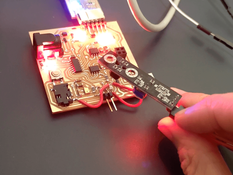
#ATtiny1614 #Phototransistor #Infrared(IR) Emitter
Assignments: (Group) 1. Probe an input device(s)'s analog and digital signals. (Individual) 2. Document your work. 3. Measure something: add a sensor to a microcontroller board that you have designed and read it.
Published on: Apr 24, 2020Last updated on: Jan 12, 2021
Group Assignment: Probe an input device(s)'s analog and digital signals
Link to Documentation Page
I used the built-in serial monitor of Arduino IDE to observe my IR receiving sensor made with an NPN-phototransistor. From the code of the Sensor Reading section, the state value of the sensor is digital, which means that it will only print either 1(HIGH) or 0(LOW) in the serial monitor.

Individual Assignment: Add a sensor to a microcontroller
Materials
| # | Name | Source | Description |
|---|---|---|---|
| 1 | ATtiny1614 * 1 | DigiKey | The main microcontroller chip. |
| 2 | Phototransistor | DigiKey | Used as an infrared(IR) receiver. |
| 3 | LED * 4 | - | Used for monitoring power/RXTX and programming. |
| 4 | Headers | - | 2.54mm male/female headers & a barrel jack power header, . |
| 5 | Infrared(IR) Lamp/Emitter | - | Used for triggering the phototransistor to send signal to the host board. |
| 6 | Capacitors | - | - |
| 7 | Resistors | - | - |
| 8 | Jumper Wires | - | - |
Build
- PCB Design: Learn more from Week 6: Electronics Design
- PCB Milling: Learn more from Week 4: Electronics Production
Programming (Code)
Programming Environment Setup: Learn more from Week 8: Embedded Programming
Phototransistor Usage
The following video I watched provides some calculation about how to design an infrared receiving sensor with an NPN-phototransistor or a photodiode plus an NPN-transistor:

Although the circuit looks simple, the value of the resistor used here affects the sensitivity of the sensor. I followed the tutorial to design my circuit in KiCad.


In the circuit, we care most about the digital output value on PHOTO pin (VPHOTO) which will output either 3.3V(HIGH) or 0V(LOW) to the serial monitor of the Arduino IDE. I summarized which value will be outputted under different scenarios.
Digital Output on VPHOTO = 0V(LOW) or 3.3V(HIGH)
In Bright Space: VPHOTO = 0V(LOW), Why: R1 consumes most of 3.3V
→ Ohms Law: V = I * R
→ 3.3V = 10k Ω * I
→ I = 0.33mA
In Dark Space: VPHOTO = 3.3V(HIGH), Why: No current goes through R1
→ No voltage drop on R1
Pin Definition
Here I defined 4 pins for programming: two of them (RX, TX) are for communicating with the serial monitor, another one (PHOTO_AVR) is the IR sensor input pin and the other one (LED_AVR) is the LED output for monitoring the sensor state.
#include <avr/io.h>
#include <util/delay.h>
#include <SoftwareSerial.h>
//Check out pins from ~/Library/Arduino15/packages/megaTinyCore/hardware/megaavr/2.0.1/variants/txy4/pins_arduino.h
#define RX    9   // *** PA2
#define TX    8   // *** PA1

SoftwareSerial mySerial(RX, TX);

#define LED_AVR PIN4_bm // PA4:LED pin
#define PHOTO_AVR PIN7_bm // Phototransistor sensor

void setup() {
  mySerial.begin(115200);
  PORTA.DIRSET = LED_AVR; //Output
  PORTA.DIRCLR = PHOTO_AVR; // Input
}
Sensor Reading
Inside void loop(), I used PORTA.IN & PHOTO_AVR to read the digital value (1 = HIGH or 0 = LOW) of the IR sensor and stored it to the state variable. Within switch/case, I defined when to blink a LED denpending on the value of the sensor state.
void loop() {
  bool state = PORTA.IN & PHOTO_AVR; // read the state of the phototransistor

  switch(state) {
    case 1:
    PORTA.OUT &= ~LED_AVR; // turn the LED OFF
    break;
    case 0:
    PORTA.OUT |= LED_AVR; // turn the LED ON
    break;
    default:
    PORTA.OUT &= ~LED_AVR; // turn the LED OFF
    break;
  }

  mySerial.println(state); // print state value in the serial monitor: 1(HIGH) or 0(LOW)
  delay(200);
 }
The IR emmiter can be an infrared lamp or LED. In the video, I adpoted an IR module and connected its power pins to an Arduino board without programming and then used it to test if my custom IR receiving sensor works. We can see that the LED is blinked once the phototransistor detects nearby infrared light.
Problem & Solution
Since the package of a SMT phototransistor is similar to a SMT LED, it is easier to place it in the wrong direction.
Before Correction
From the diagrams below, the cathode pin (usually connected to GND) of a SMT LED is marked in green whereas the collector pin (usually connected to a resistor or Vcc) of a SMT NPN-phototransistor is also marked in green, which makes it confusing during soldering. The IR receiving circuit didn't work with the phototransistor placed in the wrong direction.


After Correction
After reversing its pin drection with two jumper wires, the IR receiving sensor starts to act normally.

