Week 11: Output Devices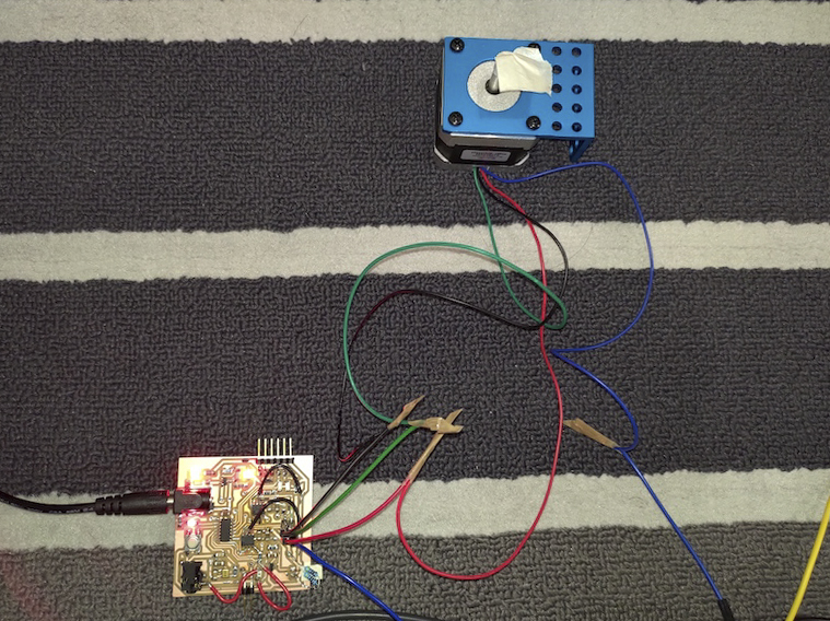
#ATtiny1614 #A4953 Stepper Driver #Stepper
Assignments: (Group) 1. Measure the power consumption of an output device. (Individual) 2. Document your work. 3. Add an output device to a microcontroller board you've designed and program it to do something.
Published on: Apr 24, 2020Last updated on: Jan 12, 2021
Group Assignment: Measure the power consumption of an output device
Link to Documentation Page
According to the A4953 stepper driver datasheet, it can provide a stepper motor with maximum 2A current which is greater than the Rated Current defined in the stepper datasheet.

Stepper motors have a Rated Voltage and Current. A typical stepper motor like NEMA 17 might have a rated voltage of 2.8 Volts and a maximum current of 1.68 Amps. This basically means if you hook it up to 2.8 Volts it will draw 1.68 Amps.

After making sure that the maximum current provided by A4953 covers the rated current of the stepper, I connected a multimeter to the board for measuring the current consumption while the stepper is moving. The connection is shown in the diagram below.

From the video, we can see that the stepper motor consumes around 600mA current at maximum which is big enough to make the A4953 driver chips heating up during longer execution. Therefore, it is recommended to stick heat sinks on the top of the chips.

Full-Step Rotation (Clockwise)
Individual Assignment: Add an output device to a microcontroller
Materials
| # | Name | Source | Description |
|---|---|---|---|
| 1 | ATtiny1614 * 1 | DigiKey | The main microcontroller chip. |
| 2 | A4953 * 2 | DigiKey | Used for driving a stepper motor. |
| 3 | LED * 4 | - | Used for monitoring output and connection states. |
| 4 | Headers | - | 2.54mm male/female headers & a barrel jack power header, . |
| 5 | 9V Power Adapter | - | Used for providing external power to the A4953 drivers. The Load Supply Voltage Range (VBB) of A4953 is between 8V and 40V. |
| 6 | Capacitors | - | - |
| 7 | Resistors | - | - |
| 8 | Stpper (SY42STH38-1684A) * 1 | Pololu (Datasheet) | - |
| 9 | Jumper Wires, Alligator Clips | - | - |
Build
- PCB Design: Learn more from Week 6: Electronics Design
- PCB Milling: Learn more from Week 4: Electronics Production
Programming (Code)
Programming Environment Setup: Learn more from Week 8: Embedded Programming
Stepper Motor Manipulation with PWM
I first watched the following video to get a brief understanding about how a stepper motor works:
The manituplation is based on changing the magnetic field inside the motor by powering coils ON or OFF in certain orders. The type of the stepper I used here is a bipolar stepper motor which has 4 wires. By giving HIGH(+) or LOW(-) pulse to the specified wires, I can rotate the stepper motor in different resolutions such as full step, half step, quarter step and 1/8 step, etc.
Full Step

Half Step

Quarter Step

Pin & Parameter Definition
Following the tables above, I defined the correspondent pins including A_PLUS(A+), A_MINUS(A-), B_PLUS(B+) and B_MINUS(B-) connected to the specified wires as well as LED_AVR connected to a LED for monitoring the rotation state.
#include <avr/io.h>

#define A_PLUS PIN0_bm //PB0, Black
#define A_MINUS PIN3_bm //PA3, Green
#define B_PLUS PIN2_bm //PB2, Red
#define B_MINUS PIN1_bm //PB1, Blue

#define NUM_STEPS 200
#define DELAY_STEP_US 2500
#define DELAY_CYCLE_MS 1000

#define LED_AVR PIN4_bm //PA4

void setup()
{
  PORTA.DIR = LED_AVR | A_MINUS;
  PORTB.DIR = A_PLUS | B_PLUS | B_MINUS;  // set these pins to outputs
}
Custom Functions with Pulse Manipulation
In order to make the code clean and easy to understand, I defined custom functions to execute digitalWrite on the specific pin(s)/wire(s).
// 1.8 degree/step, 200 steps/rev => per full_step_cw() has 4 steps(pulses)
void full_step_cw() {
  Ap();
  Bp();
  Am();
  Bm();
}

void full_step_ccw() {
  Bm();
  Am();
  Bp();
  Ap();
}
// 0.9 degree/step, 400 steps/rev => per half_step_ccw() has 8 steps(pulses)
void half_step_ccw() {
  Bm();
  Am_Bm();
  Am();
  Am_Bp();
  Bp();
  Ap_Bp();
  Ap();
  Ap_Bm();
}
// 0.45 degree/step, 800 steps/rev => per quarter_step_ccw() has 16 steps(pulses)
void quarter_step_ccw() {
  Bm();
  Am_Bm();
  Am_Bp_Bm();
  Am();
  Am_Bp();
  Ap_Am_Bp();
  Bp();
  Ap_Bp();
  Ap_Bp_Bm();
  Ap();
  Ap_Bm();
  Ap_Am_Bm();
}
/***************** Set this Lead to HIGH *****************************/
void Ap() {
  allGND();
  PORTB.OUT |= A_PLUS;
  wait();
}

void Am() {
  allGND();
  PORTA.OUT |= A_MINUS;
  wait();
}

void Bp() {
  allGND();
  PORTB.OUT |= B_PLUS;
  wait();
}

void Bm() {
  allGND();
  PORTB.OUT |= B_MINUS;
  wait();
}
/********************* Set these Leads to HIGH *************************/
void Ap_Bp() {
  allGND();
  PORTB.OUT |= A_PLUS | B_PLUS;
  wait();
}
void Ap_Bm() {
  allGND();
  PORTB.OUT |= A_PLUS | B_MINUS;
  wait();
}
void Am_Bm() {
  allGND();
  PORTA.OUT |= A_MINUS;
  PORTB.OUT |= B_MINUS;
  wait();
}
void Am_Bp() {
  allGND();
  PORTA.OUT |= A_MINUS;
  PORTB.OUT |= B_PLUS;
  wait();
}
/*********************/
void Ap_Am_Bp() {
  allGND();
  PORTA.OUT |= A_MINUS;
  PORTB.OUT |= A_PLUS | B_PLUS;
  wait();
}
void Ap_Bp_Bm() {
  allGND();
  PORTB.OUT |= A_PLUS | B_PLUS | B_MINUS;
  wait();
}
void Ap_Am_Bm() {
  allGND();
  PORTA.OUT |= A_MINUS;
  PORTB.OUT |= A_PLUS | B_MINUS;
  wait();
}
void Am_Bp_Bm() {
  allGND();
  PORTA.OUT |= A_MINUS;
  PORTB.OUT |= B_PLUS | B_MINUS;
  wait();
}
/**********************************************/
void allGND() {
  PORTA.OUT &= ~A_MINUS;
  PORTB.OUT &= ~A_PLUS & ~B_PLUS & ~B_MINUS;
}

void wait() {
  delayMicroseconds(DELAY_STEP_US);
}
Full-Step Rotation (Clockwise + Counterclockwise)
After defining the custom functions above, I only need to call certain functions to make different rotation patterns inside void loop() method and blink a LED for monitoring if the rotation is finished.
void loop()
{
  int counter = 0;

  while (counter < NUM_STEPS / 4) {
    full_step_ccw();
    full_step_cw();
    counter ++;
  }
  counter = 0;

  PORTA.OUT |= LED_AVR;  // blink the LED once the rotation is done
  delay(DELAY_CYCLE_MS);
  PORTA.OUT &= ~LED_AVR;
}
Quarter-Step Rotation (Counterclockwise)
void loop()
{
  int counter = 0;

  while (counter < NUM_STEPS / 4) {
    quarter_step_ccw();
    counter ++;
  }
  PORTA.OUT |= LED_AVR;  // blink the LED once the rotation is done
  delay(DELAY_CYCLE_MS);
  PORTA.OUT &= ~LED_AVR;
}
Problem & Solution
Initially, I spent lots of time on investigating why my custom board did't drive a stepper motor to move by measuring the output current with a multimeter. The current remained 0A all the time no matter how I changed the connection order of the stepper wires. After double checking with the A4953 datasheet, it turned out that the problem hanpped in the connection between LSS and GND pins.
Before Correction
At the beginning, I didn't connect LSS pins to GND, which made the A4953 driver stop outputing current to drive the stepper motor.


After Correction
The A4953 driver works after connecting LSS pins to GND with jumper wires.


